Experts in Design and Planning - Able Group .net.
Able Group .net; We're the Property Information Network.
Answers to Your Questions!![]() Information.
Information. ![]() Contractor Referrals,
Contractor Referrals, ![]() Consultation,
Consultation, ![]() Job Costs.
Job Costs.
![]() South Jersey's Worker Referral Network, Your Community Forum for Seashore Businesses.
South Jersey's Worker Referral Network, Your Community Forum for Seashore Businesses.
|
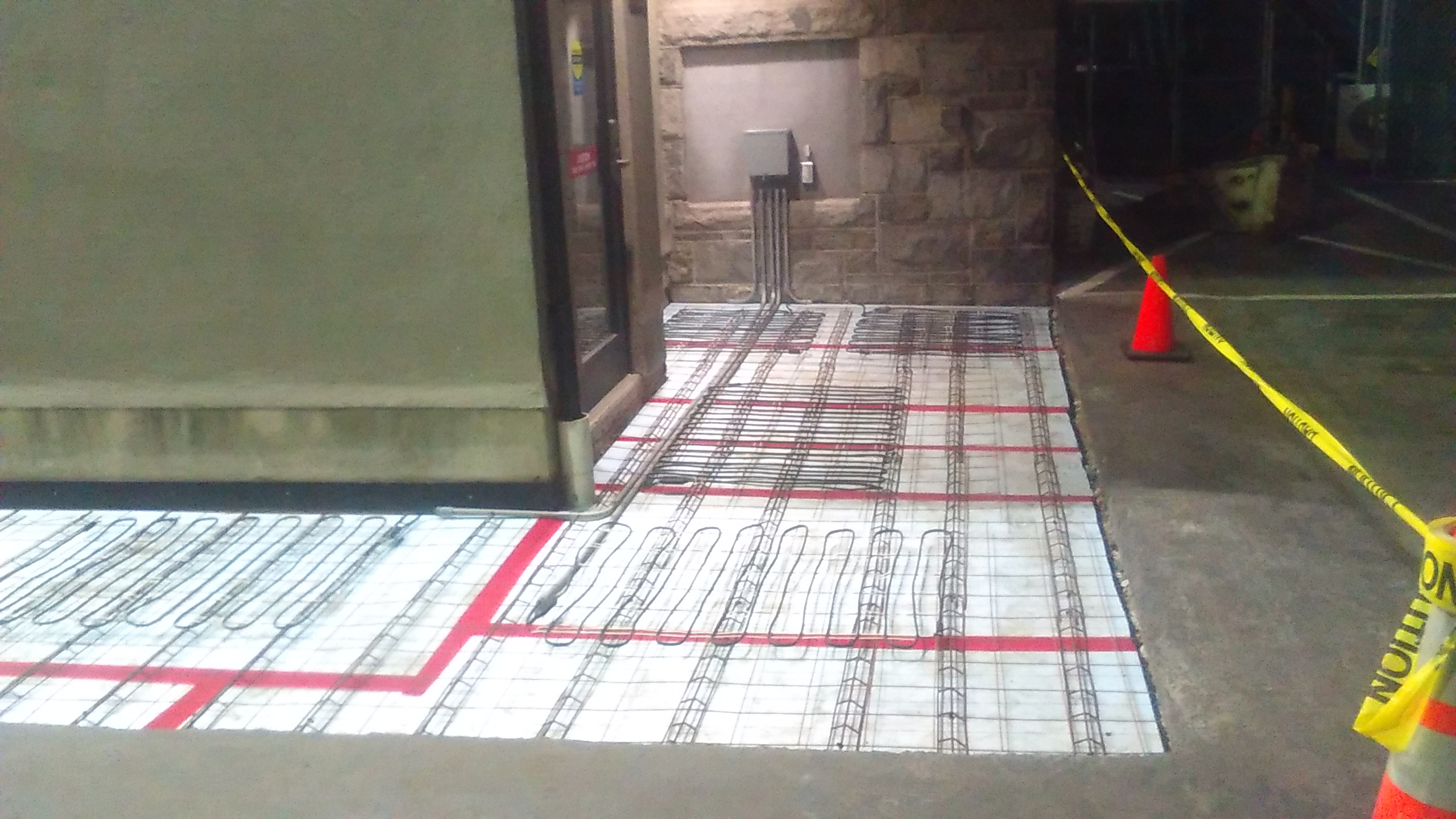
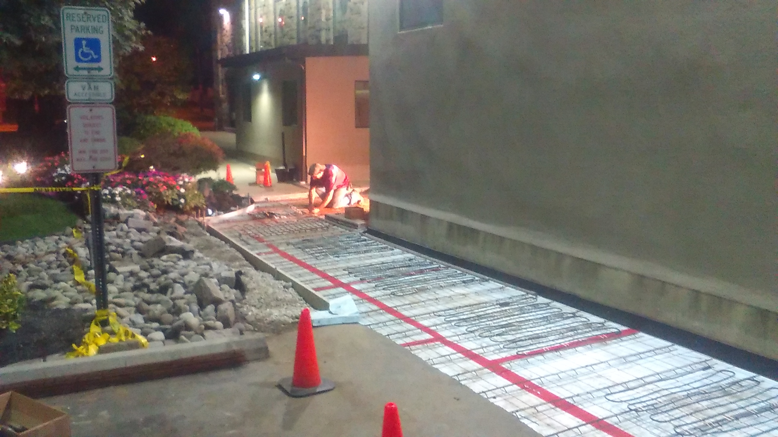
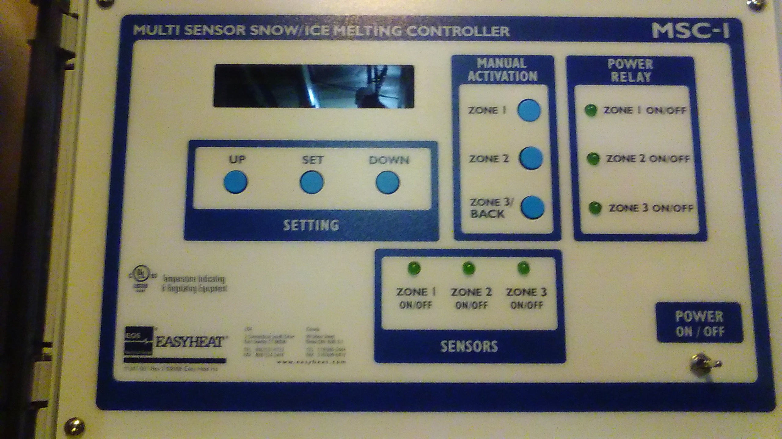
Snow Melt - Electrically Heated Sidewalks or Walkways - WE HELP YOU. Service or Costs: The in-ground sensor is encased within a rugged enclosure and is intended to be embedded within the surface being heated, usually concrete or asphalt. The moisture sensor is supplied with a protective field cover to simplify asphalt or concrete installations, and comes with 30' of wire for connection back to the
heater sensor control unit. The sensor has an
integral 1/2" NPT conduit connection. The moisture sensor connection wire may be extended up to 500' with an appropriately rated 18-20AWG 4 wire shielded cable. The low voltage moisture sensor senses falling or drifting snow by melting it on the "grid" area of the sensor and then detecting the presence of moisture by measuring an electrical signal between the grid bars. The moisture sensor also measures the
temperature of the surface. This "dual sensing" technique allows the heater sensor to control the heating equipment (mats, cables, etc.) in the optimum manner possible. This assures minimum energy costs while still providing reliable surface snow detection. Snow melting systems are designed to melt snow and ice in outdoor locations, such as driveways, parking ramps, sidewalks, steps, etc. The mats are expected to be completely embedded in asphalt or concrete surfaces. Snow melting systems can be installed under pavers. The intended installations are residential walks,
patios, and driveways. The mats contain an electrical heating element designed to provide a fixed amount of heat. When connected to appropriate system voltage, and when a system control detects the presence of ice or snow, the mats are energized. Then, heat from the mats increases the surface temperature of the pavement to above freezing, melting snow or ice on the surface. When controlled
by the controls, the mats provide economical and reliable snow and ice melting performance. These mats are embedded in conjunction with the paving installation. Some control and accessory devices may also require installation at this same time. The mats are comprised of a single length of heating cable formed into a rectangular shape (except custom mats can be almost any shape) and secured in this shape by
polymer carrier strands fused to the cable. Cold leads are factory connected to the mat and are available in various lengths to suit the location of electrical connection boxes. The mats are available in both standard and custom sizes (length, width, power, voltage, etc.). Thermal insulation is not required beneath these mats, but will improve the performance and operating cost
efficiency of the installation by reducing back losses. Consult with architect/engineer to ensure structural integrity of any thermal insulation. Each installation must have a mat layout plan and mat wiring plan prior to beginning the installation. This information will ensure that all necessary mats are available at the site prior to paving, and that all mats correspond to the installation requirements (shape, power supply voltage, etc.). The mat layout plan must clearly identify the following: The mat wiring plan must clearly identify the following: The mat layout must be designed to cover the area to be protected, and allowance must be made for obstructions, such as light poles, expansion joints, control joints, etc. In some cases such obstructions can be accommodated by modifying mat shape. Mats must be laid in accordance with the mat layout plan to which they were manufactured: this plan must be available at the job site. Identify location for expansion and control joints. Concrete forms may be inaccurate, so allow 2-4" on each side of the mats
for clearance. Allow approximately 4 inches between adjacent mats at expansion and control joints. For asphalt, mats must be placed at least 12" in from edges to accommodate variations in edging. Adjacent mats may be positioned within 2", but must not touch or overlap. Mats must not be placed under areas to be drilled
in the future for fastening of surface mounted structures, such as hand railings. Control joints are typically indentations in a concrete surface along which cracks are intended to form. The indentations may be formed by special trowel prior to hardening of the concrete, or by cutting with a special concrete saw after concrete has set. Cracking at control points and subsequent movement of adjacent sections could
damage a mat crossing a control joint; therefore, mats must not be intentionally positioned through control joints. In case of unintentional shifting of mats during pour, control joints must not be sawn closer than one inch above mats to ensure that mat heater cable is not damaged by the saw. Expansion joints are,
typically, formal separations between sections of concrete, with some flexible
material forming the separation which then absorbs any thermal expansion in the
concrete section. Movement of adjacent sections could damage a mat crossing an
expansion joint, hence, mats must not be positioned through expansion joints. Appropriate wiring of
all mats must be completed according to the mat wiring plan. Conduit must be
used to protect the non-heating leads at the exit from the installation area to
the junction boxes. All necessary conduit and other wiring devices to be
installed within the surface must be available prior to beginning mat/surface
installation. In most cases the ideal location for junction boxes is indoors
with at least 18" of accessible mat leads within the box. When planning the
location of the junction boxes it is important that at least one foot of mat
cold lead remains embedded in the asphalt or pavement. Junction boxes and
conduit should be located so that they can accommodate the maximum number of mat
leads expected to be routed to/through them. Insulating bushing must be used to
protect the cold lead where it enters conduit. Controls/wiring must be
installed according to the mat wiring plan and mat layout plan. (Some controls
include devices required to be installed in the heated surface). All wiring must
conform to Local and National Electrical Codes. If the mats are controlled
simply by manual electrical switches, it is recommended that a pilot lamp be
installed on the load side of each switch so that there is a visual indication
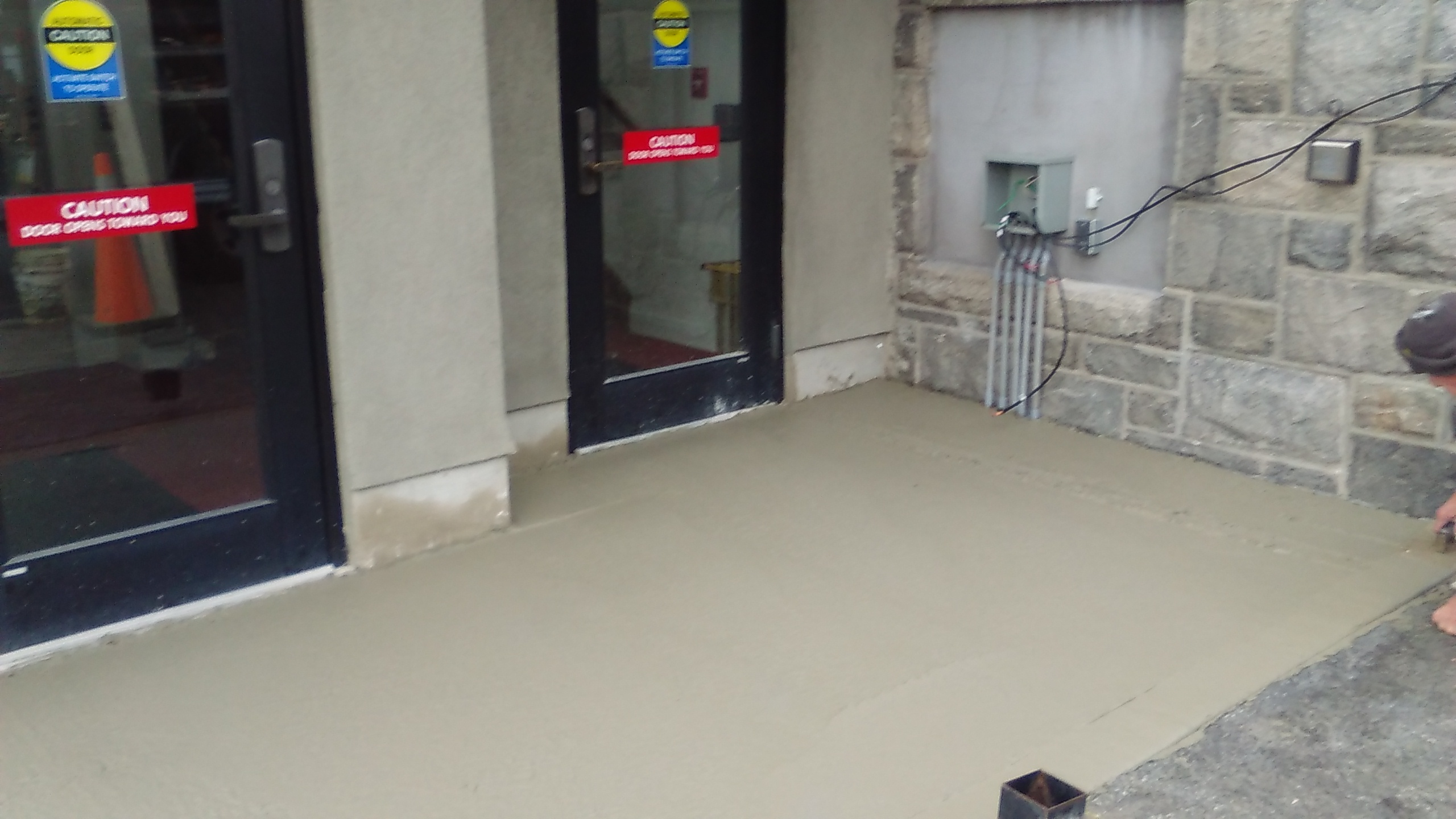
when the mats are energized. The pavement must be
installed in accordance with proper construction practices, including allowance
for drainage, reinforcement, etc. Improper pavement installations can result in
unstable surfaces which can crack/move and break mat heating cables; warranty is
void in such situations. Concrete installations must not contain aggregate
greater than .75". The distance from the
finished surface to the level at which the mats are placed is defined as the
"mat placement depth". The mat placement depth must not be greater than 3 1/2"
(to ensure adequate surface heating) nor less than 1 1/2" to ensure complete
containment of the mats within the surface covering. Typically, a base layer of
concrete is poured and leveled, then the mats are immediately positioned, and
then the remaining concrete is poured. It is also possible to allow the base
layer of concrete to set, then position the mats and complete the pour. If the
second pour is inordinately delayed, a binder or binding agent should be
employed to minimize shear plane formation. Asphalt installation must not
contain aggregate larger than 3/8" and must be delivered to the job site at a
temperature less than 340 degrees Fahrenheit - larger aggregate and/or higher
temperatures will damage cable and result in failure. Typically, a base layer of
asphalt is laid and allowed to set, then the mats are positioned, and then the
final layer of asphalt is laid. (It is also possible to lay mats on an existing
layer of asphalt that is being resurfaced). The mats must be located between 3
1/2" and 1 1/2" of the finished surface to ensure adequate surface heating. Extreme care must be
used when machinery such as wheelbarrows, rollers, front-end loaders, tractors,
paving machines, etc. is involved in the installation of heating cables/mats in
asphalt or concrete surfaces. Such machinery must not have cleats of any type
nor metal tracking of any type, as such cleats/tracking can sink into the
asphalt and contact the mat, possibly damaging the cable. The use of sharp
implements, such as rakes, shovels, etc., is usually required during surface
installations. However, unless care is taken, these can damage mats during
installation. All workers must be advised to avoid contacting the mats with such
implements, and that, if they do, the mat must be immediately checked for
damage. Do not route
wheelbarrows, rollers, trucks, etc. over uncovered mats. It is recommended that
workers not walk on the mats. When mats are installed on rebar or in other
situations where weight on the mats would be highly concentrated, damage to the
cable is possible that would result in immediate or later operational failure.
Local electrical inspectors may require inspection prior to, during and/or after
surface installation. Be certain that they are contacted prior to beginning mat
installation. Electrical panels and
controls must be identified as to their snow melting function. Snow melting
areas must be identified by clearly visible signs or marking. Pavement
identification nameplates are available. Do not use admixtures or chemical
compounds that may be harmful to copper or PVC. Snow melting units are approved
for use in wet locations. The heater-to-cold-lead wire splices made at the
factory are designed and tested to be waterproof. To ensure a completely
waterproof installation, it is also important that all field connections must be
waterproof. The use of approved exterior type junction boxes, fittings and
bushings plus care in waterproofing splices will assure a reliable and
trouble-free electric performance. It is required that all products listed by UL
and CSA be properly indentified. Therefore, if the leads on these mats are
shortened, ensure that a minimum 6" of cold lead with the identification tag is
retained within the junction box. Mats may be tailored to
follow contours of curves and other obstructions by making a series of cuts to
the mat carrier strands. Extreme care should be exercised to prevent cutting the
mat heater wire during this operation. Start all cuts on the
side opposite the cold lead and cut strands towards the cold lead side. To make
a curve, cut strands. The number of strand cuts will depend on the mat length
and surface curvature. In the same way, mat shape can be altered to form a wider
block pattern or to go around an object. To ensure adequate heating, do not
allow cable spacing at outer edge of curve to be more than 2 times the standard
cable spacing. Site/Mat Preparation: The continuity and
insulation resistance of each mat must be tested prior to paving. Record
readings. Connect a megger between the copper grounding braid and the inner
conductor on one lead of a mat. Ensure the other lead of the mat is isolated and
that the heating element is not in contact with the ground braid. Set the megger
at 500 V (minimum) and measure the resistance. The resistance must be 10 Megohms
minimum. This test assures that the mat has not been damaged during shipment or
subsequent handling. Next connect an ohmmeter between the inner conductors of
the two leads of the mat. Measure the resistance of the mat. Be certain that the
mat resistance is appropriate for the marked wattage and voltage. Repeat above
test for each mat used in the installation. Position all mats associated with
the surface installation according to the mat layout plan and mat wiring plan.
Thread mat cold lead wires through conduit into associated junction box. Lay
mats in position to check original layout and spacing. Leave sufficient slack in
lead wires to permit handling of mats. Lay mats aside temporarily to allow for
installation of base layer of surface material. If necessary, provide protection
for any controls which may get damaged or dislocated during pour. Installation in
concrete: Installation in
asphalt: Installation in
concrete steps: Installation under
pavers: Proper preparation of
the soil and aggregate base and the use of edge restraints to prevent loss of
sand are critical. Loss of sand may result in mat failure. Secure the mat to a
wire fabric with nylon cable ties attached to the WHITE MAT STRANDS ONLY
wherever possible. If ties must be used on the black heating cable, leave
slightly loose, DO NOT fully tighten or the tie may cut into the cable and
result in failure of mat in operation. Lay the mats on top of either the
compacted aggregate base (patio/walkway type installation) or the concrete base
(driveway type installation) and cover with sand. The mat heating cable and
splice to the non-heating leads must be fully contained in the sand bed. Retest
mats according to initial testing. Non-heating leads having
a grounding sheath or braid should be permitted to be embedded in the masonry or
asphalt in the same manner as the heating cable without additional physical
protection. All but 1 inch to 6 inches of non-heating leads not having a
grounding sheath should be enclosed in a rigid metal conduit, electrical
metallic tubing, intermediate metal conduit, or other raceways within asphalt or
masonry. The distance from the factory splice to raceway should not be less than
1 inch or more than 6 inches. Insulating bushings should be used in the asphalt
or masonry where leads enter conduit or tubing. Leads should be protected in
expansion joints and where they emerge from masonry or asphalt by rigid conduit,
electrical metallic tubing, intermediate metal conduit, other raceways, or other
approved means. Not less than 6 inches of free non-heating lead should be within
the junction box. Power supply non-heating leads (cold leads) for resistance
elements should be identified for the temperature encountered.
Electrically Heated Sidewalks
Apply warning labels "CAUTION - ELECTRIC SNOW AND ICE MELTING" to power supply and adjacent to the heated surface. Surfaces should be inspected annually for cracks, exposed cable, etc., and sealed as required with suitable cement or asphalt-compatible
material. Should grass or weeds develop in the gaps between pavers, care must be taken when using tools to remove them or the mat may be damaged. Fixed outdoor electric deicing and snow melting equipment
Electric
heating equipment should be installed in such a way as to be protected from
physical damage. External surfaces of outdoor electric deicing and snow melting
equipment that operate at temperatures exceeding 140 degrees Fahrenheit should
be physically guarded, isolated, or thermally insulated to protect against
contact by people in the area. The presence of outdoor electric deicing and snow
melting equipment should be evident by the posting or appropriate caution signs
or markings where clearly visible.
Resistance Heating
Elements Units, panels, or cables
should be installed as follows: Cables, units, and
panels should be secured in place by frames or spreaders or other approved means
while the masonry or asphalt finish is applied. Cables, units, and panels should
not be installed where they bridge expansion joints unless provision is made for
expansion and contraction. Heating element assemblies should be secured to the
surface being heated by approved means. Where the heating element is not in
direct contact with the surface being heated, the design of the heater assembly
should be such that its temperature limitations should not be exceeded. Heating
elements and assemblies should not be installed where they bridge expansion
joints unless provision is made for expansion and contraction. Where installed
on flexible structures, the heating elements and assemblies should have a
flexural capability that is compatible with the structure. | ||||||||||


.JPG)